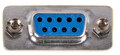
Распиновка Cisco/Juniper/Zyxel RJ45 Serial Console port to DB9 female
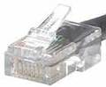
Network devices with RJ45 console ports typically follow the Cisco pin out. The pinout below shows a null modem wiring between the RJ45 and the DB9 female connector. This is known to work on Cisco, Juniper, Zyxel and Ubiquiti Edge series devices with RJ45 console ports. If you are using UTP network cable then colour coding
| RJ45 Pin Number | RJ45 Pin Name | DB9 Pin Number | DB9 Pin Name | Description | CTS | Request To Send -> Clear To Send | Orange/White | Green/White | ||||||
|---|---|---|---|---|---|---|---|---|---|---|---|---|---|---|
| 2 | DTR | 6 | DSR | Data Terminal Ready -> Data Set Ready | Orange | Grn | ||||||||
| 3 | TXD | 2 | RXD | Transmit Data -> Receive Data | Green/White | Orange/White | ||||||||
| 4 | GND | 5 | GND | Ground | Blue | Blue | ||||||||
| 5 | GND | 5 | (tie pins 4/5 on RJ45 to Pin 5 on DB9 | Blue/White | Blue/White | |||||||||
| 6 | RXD | 3 | TXD | Receive Data Data Terminal Ready | Brown/White | Brown/White | ||||||||
| 8 | CTS | 7 | RTS | Clear To Send Receive Data | Green/White | Orange/White | ||||||||
| 5 | GND | 5 | GND | Ground | Blue/White | Blue/White | ||||||||
| 6 | RXD | 3 | TXD | Receive Data
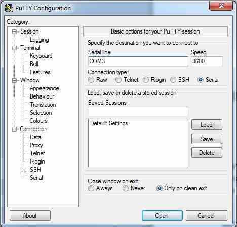
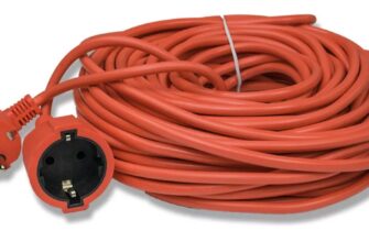
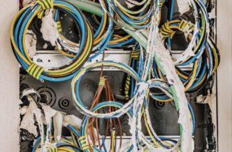
На эту распиновку нет ни одного отзыва! Если вы знаете, правильная она или нет, — нажмите на соответствующую кнопку ниже. Источник NateksПодключение с помощью консольного кабеля PrintModified on: Mon, 8 Feb, 2021 at 5:24 PM Для подключения к коммутатору вам понадобится консольный кабель от коммутатора, который идет в комплекте с ним. Очень часто этот кабель бывает утерян. Консольный кабель от другого оборудования (например, от Cisco, Juniper) не подойдет. Ниже представлены распайки консольных кабелей — miniUSB и RJ45 — для их самостоятельного изготовления. Далее подключитесь к коммутатору, воспользовавшись инструкцией ниже. Подключите физически ПК с установленным ПО Putty (или аналогами) к маршрутизатору консольным кабелем, идущим в комплекте с оборудованием, в порт CONSOLE маршрутизатора. При отсутствии COM-порта на ПК используйте дополнительный кабель usb2com, внешний вид которого показан на изображении ниже. Таким образом, схема подключения следующая:
Источник CTP2000 Series Console Cable PinoutsThe console port CTP2008, CTP2024, and CTP2056 devices with the new PP833 processor uses a USB-type connector located on the right of the PP833 faceplate labelled “RS-232”. CTP2000 series devices with the PP310 and PP332 processors use an RJ-45 connected to the COM2 port. This cable must be connected during the first boot process. Use a shielded cable for the COM2 port on the CTP2056 device. Figure 1 displays the console cable pin configurations for CTP2000 series devices with the PP310 and PP332 processors. On the left is the RJ-45 connector, and on the right is the DB-9 connector with the pin numbering indicated. The console connections are configured to the following parameters: Flow control: Xon/Xoff Figure 1: CTP2000 Series Console Cable Pin Configurations for PP310 and PP332 Processors
Table 1 and Table 2 list console cable pinouts for CTP2000 Series devices based on the pin configurations. Table 1: CTP2000 Series Console Cable Pinouts for PP310 and PP332 Processors
|